
Briggs & Stratton engines often require valve guide attention; repair kits, like part number 19232, are readily available for common 5/16” stems.
What are Valve Guides?
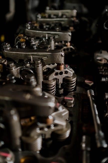
Valve guides are crucial components within a Briggs & Stratton engine, serving as precision-fit sleeves installed within the cylinder head. Their primary function is to maintain accurate valve alignment during the engine’s operational cycles – intake and exhaust. These guides ensure the valves move straight, preventing contact with the piston or cylinder walls, which would lead to significant engine damage.
Typically constructed from durable materials like cast iron or bronze, valve guides withstand considerable heat and wear. They provide a low-friction surface for the valve stems to glide along, contributing to efficient engine performance and longevity. Proper valve guide function is essential for maintaining compression, maximizing power output, and minimizing oil consumption within the engine.
Why Valve Guides Fail
Valve guide failure in Briggs & Stratton engines commonly stems from several factors. Continuous exposure to high temperatures and the abrasive action of valve stem movement contribute to wear over time. This wear creates excessive valve stem-to-guide clearance, leading to valve wobble and reduced sealing efficiency.
Another cause is the buildup of carbon deposits, which exacerbate wear and hinder proper valve seating. Lack of lubrication, often due to infrequent maintenance or oil contamination, accelerates the deterioration process. Furthermore, physical damage from improper valve adjustments or foreign object debris can compromise guide integrity. Ultimately, failing valve guides result in reduced engine power, increased oil consumption, and potential internal damage.
Symptoms of Bad Valve Guides
Identifying failing valve guides in a Briggs & Stratton engine requires attention to specific performance indicators. A noticeable symptom is excessive oil consumption, as worn guides allow oil to seep past the valve stem seals. This often manifests as blue smoke emanating from the exhaust, particularly during startup or acceleration. Reduced engine power and compression are also common, stemming from poor valve sealing.
Furthermore, a distinct “ticking” or “clattering” sound from the valve train can indicate valve stem wobble within worn guides. Backfiring, especially through the carburetor, may occur due to improper combustion caused by leaky valves. Finally, a general decline in engine efficiency and difficulty starting can signal the need for valve guide inspection and potential repair.
Identifying the Correct Repair Kit
Accurate engine model identification is crucial for selecting the right Briggs & Stratton valve guide repair kit, often starting with part number 19232.
Determining Your Engine Model Number
Locating your Briggs & Stratton engine’s model number is the first, and arguably most important, step in procuring the correct valve guide repair kit. This number ensures compatibility and prevents ordering incorrect parts. The model number is typically found on the engine’s valve cover or blower housing.
Look for a sticker or stamped marking containing a series of numbers and letters. It’s vital to record this number accurately, as even a slight variation can lead to issues. Once you have the model number, you can consult Briggs & Stratton’s parts diagrams or online resources to confirm the appropriate repair kit for your specific engine. Don’t assume a kit for a similar engine will fit; always verify with the model number.
Briggs & Stratton Part Number 19232: A Key Kit
Part number 19232 is a frequently recommended repair kit specifically designed for Briggs & Stratton engines utilizing 5/16-inch valve stems. This kit generally includes the necessary reamers, valve guides, and pullers required to effectively address worn or damaged valve guides. It’s considered a comprehensive solution for many common engine repairs.
However, it’s crucial to remember that while 19232 is a popular choice, verifying compatibility with your engine’s model number is paramount. The kit may not be suitable for all Briggs & Stratton engines. Always double-check the parts list and specifications to ensure it aligns with your engine’s requirements before purchasing and beginning the repair process.
Bushing Part Number 231218: Specific Applications
Bushing part number 231218 is often mentioned in conjunction with valve guide repair, particularly when addressing specific engine models. While part number 19232 provides a broader kit, 231218 represents a specific bushing component that may be necessary depending on the extent of the wear and the engine’s configuration.
Determining if your engine requires bushing 231218 necessitates a careful review of your engine’s model number and a thorough inspection of the valve guides themselves. It’s not a universal replacement; its application is model-dependent. Consulting a Briggs & Stratton shop manual or parts diagram is highly recommended to confirm compatibility before ordering and installing this specific bushing.
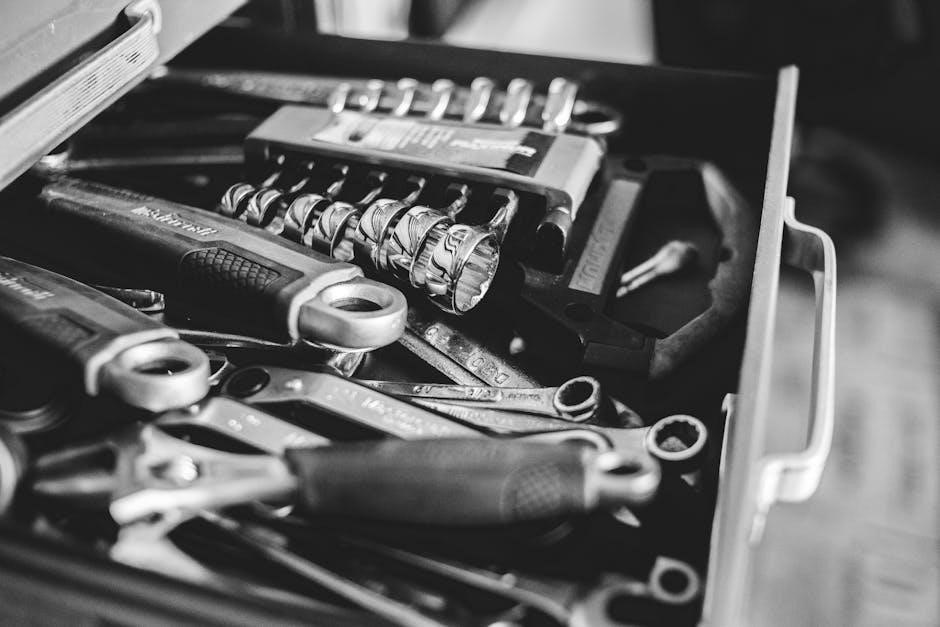
Tools Required for Valve Guide Repair
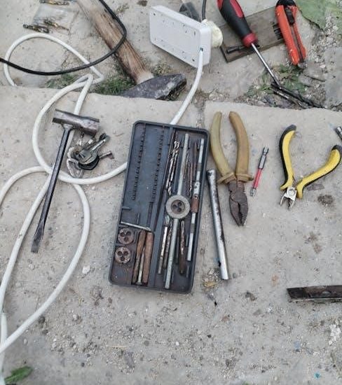
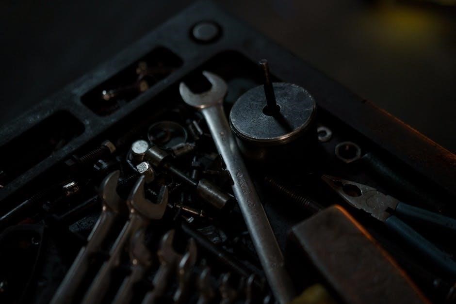
Essential tools include reamers, pullers, and a valve guide reject gage for proper fit; specialized tools from Beck Tools can also aid the process.
Essential Reamers and Pullers
For successful valve guide repair on Briggs & Stratton engines, having the correct reamers and pullers is absolutely critical. The repair kit, specifically part number 19232 for 5/16” stems, often includes these essential components. Reamers are used to precisely size the valve guide bore to ensure a proper fit with the valve stem, preventing excessive wear and maintaining optimal sealing.
Valve guide pullers are equally important for safely removing the old, worn guides without damaging the cylinder head. Attempting removal without the proper puller can lead to costly head damage. Different puller designs may be required depending on the engine model, so verifying compatibility is key. Investing in a quality set of reamers and pullers will significantly streamline the repair process and contribute to a long-lasting, reliable repair.
Valve Guide Reject Gage: Ensuring Proper Fit
A Valve Guide Reject Gage is an indispensable tool when performing Briggs & Stratton valve guide repairs, guaranteeing a precise and functional outcome. This specialized gauge verifies the internal diameter of the newly installed valve guides, confirming they meet factory specifications. Using this tool prevents issues like valve stem binding or excessive oil consumption, both common consequences of improperly sized guides.
The gage determines if the guide bore is within acceptable tolerances. If the guide fails the gage test, it indicates the guide is either too small or too large, necessitating replacement. Proper fit is paramount for optimal engine performance and longevity. Don’t skip this crucial step; it’s a small investment that prevents larger, more expensive problems down the road.
Specialized Tools from Beck Tools
Beck Tools offers a comprehensive suite of specialized tools specifically designed for Briggs & Stratton valve guide repair, streamlining the process and ensuring professional results. Their kits often include essential components like valve guide drivers, extractors, and reamers, tailored to various Briggs engine models. These tools simplify the removal of worn guides and the precise installation of new ones.
Investing in Beck Tools can significantly reduce repair time and minimize the risk of damaging engine components. Their precision-engineered tools provide a secure grip and accurate alignment, crucial for a successful valve guide replacement. A YouTube video demonstrates their use, showcasing the efficiency and effectiveness of their specialized equipment for Briggs & Stratton engine maintenance and repair.

Step-by-Step Valve Guide Repair Process
Begin by removing the cylinder head, then extract the old valve guides using appropriate pullers, and finally, carefully install the new guides.
Removing the Cylinder Head
Prior to removing the cylinder head on a Briggs & Stratton engine for valve guide repair, ensure the fuel tank is empty or the fuel shutoff valve is firmly in the OFF position – a crucial safety precaution. Disconnect the spark plug wire to prevent accidental starting. Carefully detach any linkages connected to the cylinder head, such as the governor spring or throttle cable.
Next, systematically remove the bolts securing the cylinder head to the engine block, noting their positions for reassembly. Gently tap the head with a rubber mallet if it’s stuck, avoiding forceful impacts that could cause damage. Once loose, lift the cylinder head straight up, being mindful of the gasket which may adhere to either surface. Inspect the gasket for signs of failure, which often contribute to valve guide issues.
Extracting the Old Valve Guides
With the cylinder head removed, extracting the old valve guides requires a specialized puller, often included in Briggs & Stratton repair kit 19232. Secure the cylinder head firmly in a vise. Attach the valve guide puller, ensuring it’s properly aligned with the guide. Slowly and steadily apply pressure using the puller’s screw or hydraulic mechanism.
Avoid excessive force, as this can damage the cylinder head. If the guide is particularly stubborn, applying penetrating oil around its base and allowing it to soak can help loosen it. Once the guide begins to move, continue pulling it straight out of the head. Inspect the guide bore for any remaining debris or corrosion before proceeding to installation of the new guides.
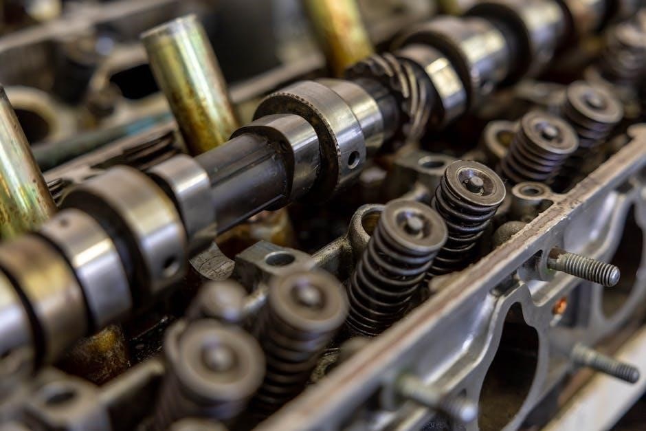
Installing New Valve Guides
Before installing new valve guides, ensure the guide bores in the cylinder head are clean and free of any debris. Lightly lubricate the new valve guides with engine oil. Using a driver tool – often part of kit 19232 – carefully press the new guide into the bore. Ensure the guide is seated fully and squarely within the head.
Avoid tilting or misaligning the guide during installation, as this can cause binding. After installation, verify the guide’s height is correct, referencing the Briggs & Stratton repair manual. Reaming may be necessary to achieve the proper fit and alignment, utilizing the reamers included in the repair kit for optimal valve stem clearance.

Additional Parts to Consider
Alongside valve guide repair, consider replacing valve springs (part 691270) and retainers (691997) for a comprehensive engine overhaul and improved performance;
Valve Spring Replacement (Part 691270)
During a valve guide repair, proactively replacing the valve springs – specifically Briggs & Stratton part number 691270 – is highly recommended. Valve springs lose tension over time, impacting engine compression and overall performance. Worn springs can contribute to valve float, leading to reduced power and potential engine damage.
Replacing them alongside the valve guides ensures a fully refreshed valve train. New springs maintain proper valve closure, optimizing combustion efficiency. This preventative measure extends the life of the repaired valve guides and maximizes the benefits of the overall engine restoration. Don’t overlook this crucial component for a truly reliable repair!
Valve Retainer Replacement (Part 691997)
Alongside valve spring replacement, consider replacing the valve retainers using Briggs & Stratton part number 691997 during your valve guide repair. These retainers secure the valve springs and play a vital role in maintaining correct valve timing and preventing valve train instability. Over time, retainers can experience wear or develop cracks, potentially leading to valve failure.
Replacing them ensures a secure and reliable connection between the valve spring and the valve stem. This proactive step minimizes the risk of valve-related issues and contributes to a smoother, more efficient engine operation. A new retainer, combined with a fresh spring, completes a comprehensive valve train overhaul, maximizing the longevity of your repair.
Bushing-Valve Guide (Exhaust) Options
When addressing valve guide wear, particularly on exhaust valves, consider bushing options alongside complete guide replacement. Briggs & Stratton offers specific bushings designed to restore proper valve stem clearance within worn guides. These bushings, like the exhaust valve guide bushing, provide a cost-effective alternative to full guide replacement in some cases.
However, the suitability depends on the extent of the wear. Severely damaged guides typically necessitate complete replacement. Ensure the chosen bushing precisely matches your engine model for a proper fit and optimal performance. Utilizing the correct bushing restores valve train geometry, reducing oil consumption and improving exhaust gas flow, ultimately enhancing engine efficiency and reliability.

Briggs & Stratton Repair Manuals & Resources
Form MS-6341-8/04 provides detailed time analysis for repairs, while Vanguard V-Twin manuals (series 290400, 294400, 290700) offer comprehensive guidance.
Form MS-6341-8/04: Time Analysis Repair Guide
Briggs & Stratton’s Form MS-6341-8/04 is a crucial resource for technicians, offering a detailed breakdown of labor times associated with various engine repairs. This 16-page document specifically aids in estimating the time required for valve guide repairs, including removal of the cylinder head and extraction/installation of guides. It’s invaluable for accurate job costing and scheduling.
The guide meticulously outlines each step involved, allowing for precise time allocation. Understanding these time allowances is essential for professional service centers and even DIY enthusiasts aiming for efficient repairs. Utilizing this form ensures a realistic assessment of the work involved when addressing worn or damaged valve guides, ultimately contributing to a streamlined and cost-effective repair process.
Vanguard V-Twin Engine Manuals (Series 290400, 294400, 290700)
Briggs & Stratton Vanguard V-Twin engine manuals, covering series 290400, 294400, and 290700, are indispensable for comprehensive valve guide repair. These manuals provide detailed exploded views, parts lists, and step-by-step instructions specific to these powerful engines. They are crucial for identifying the correct valve guide repair kit components, like bushing 231218, and understanding the unique assembly procedures for V-Twins.
Accessing the correct manual ensures proper torque specifications and clearances are maintained during reassembly. These resources detail the intricacies of overhead valve (OHV) engines, enabling accurate diagnosis and repair of valve train issues. Proper referencing of these manuals is vital for a successful and lasting valve guide repair.
Safety Precautions
Always ensure the fuel tank is empty, or the fuel shutoff valve is completely OFF, before commencing any Briggs & Stratton valve guide repair work.
Fuel Tank Empty or Shutoff Valve OFF
Prioritizing safety is paramount when undertaking any repair involving a Briggs & Stratton engine, especially valve guide work. A critical precaution involves the fuel system. Before beginning disassembly or any work on the engine, absolutely ensure the fuel tank is completely empty. This eliminates the risk of fuel spillage during the process, preventing potential fire hazards.
If completely emptying the tank isn’t immediately feasible, verify the fuel shutoff valve is firmly in the OFF position. This effectively isolates the fuel supply, mitigating the risk of leaks. Briggs & Stratton Power Products Group, LLC explicitly states this as a necessary step in their repair guidelines. Ignoring this precaution could lead to dangerous situations, so double-check before proceeding!